CIR transmission and capture with ordinary 20 kHz audio equipment
This method works with IR carrier frequency of up to 40 kHz. Most remotes are 36 (RC5/6), 38 (NEC and many others) or 40 (Sony) kHz.
The illustrations below depict a 40 kHz carrier. That is the maximum possible with 20 kHz bandwidth audio.
40 kHz IR carrier using 20 kHz audio
A single cycle of a sine wave.
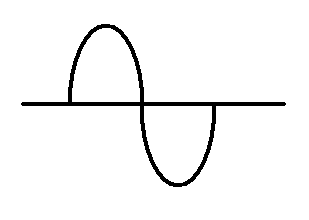
50 uS period at 20 kHz

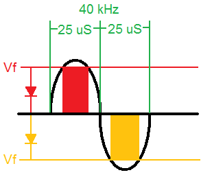
An IR LED will illuminate when the voltage exceeds it's Vf.


An IR LED wired with the opposite polarity will illuminate during the second half of the cycle.


Two IR LEDs wired with opposite polarity will produce an IR pulse twice during each cycle of the sine wave. The frequency is effectively doubled.

Using two sine waves with 180 degree phase offset will double the voltage (bridged amplifier).


40 kHz IR capture with 20 kHz audio
This circuit will convert the IR carrier to a half frequency pseudo sine wave
The carrier frequency is divided by a 74HC74 flip flop. A crude sine wave is created by four NAND gates and resistors. The limited bandwidth of the audio equiment will result in a good looking sine wave.

Breadboard construction of prototype circuit

Output of the circuit

Playback output of the soundcard. The high frequency content of the capture circuit has been removed.

Digital samples and the waveform they represent.

Complete key code

A microcontroller can be used to simplify the circuit
An IR LED is used as the photodetector, and a visible LED activity indicator has been added.

Schematic and firmware